Introduction
This article is about cheap usb gpio board based on very cheap arduino clones. The reason why I done this is that I wanted to have very cheap board with gpio that I can connect to regular pc or laptop and start experimenting with stuff. Cheap arduino uno clones costs around $4 so it’s very cheap and it has big possibilites. Also the another reason is that I wanted to have cheap board where I could have non wellknown interfaces like MDIO. There are gpio based implementation for these interfaces already in linux kernel (for example MDIO), so we need only gpio pins to simulate the rest. I don’t expect that it will be fast. The goal is to get it very cheap and it work well enough.
How to build this
Only hardware requirement is arduino uno. Good for this are cheap clones of arduino (price ~$4) that you can buy on ebay and aliexpress.
Cheap clones are using chip ch340 which might be better* than orginal arduino where atmega8 is used as chip doing usb-ttl conversion.
*Verify needed
Install program on board
Source code for board you can find here: https://github.com/matbaj/gpio-uart-board
To install it just simply clone repository and connect board to computer and then just simply:
gpio-uart-board $ make flashIt will compile code and flash board.
At this point you can just simply send bytes according to documentation included in main.c
Linux part
To get this device as gpio_chip you will need to install module which will send bytes to this device, when there will be action from gpio side.
Module source code you can find here: https://github.com/matbaj/gpio-uart-module
To install it you will need clone it and type:
gpio-uart-module $ make
gpio-uart-module $ sudo make modules_install
After this you need load this module as root:
$ sudo modprobe gpio_uartAt this point you have running module but you still need attach somehow device to this module. This module is based on serio component, so for this you will need use inputattach. Currently there is no support for this module in inputattach and you need to compile it from sources with small modification.
I have forked this project and I put this on github with gpio-uart module support: You can find it here: https://github.com/matbaj/linuxconsole
Clone this repository and run:
linuxconsole $ makeIf You have already loaded gpio-uart module then You just simply write:
linuxconsole $ ./utils/inputattach --gpio-uart /dev/ttyUSB0Where /dev/ttyUSB0 is arduino device.
After this command gpio_chip is initialized
You can quickly check that You have gpio_chip0 in /sys/class/gpio/
If You want turn on led then:
~# echo 5 > /sys/class/gpio/export
~# echo out > /sys/class/gpio/gpio5/direction
~# echo 1 > /sys/class/gpio/gpio5/value
You should see that led is turned on on arduino board.
Testing
This approach shouldn’t be used as proffessional usecases. You have been warned.
First test that I made was puting up and down into while loop without any delay for led pin and I run this. After this I just connected oscilloscope to this pin and check results. It isn’t stable and I got frequency between 67kHz and 77kHz
Here is screenshot from oscilloscope:
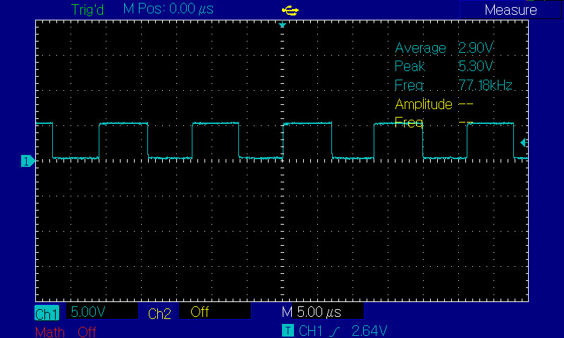
The reasons why I warn is the picture below:
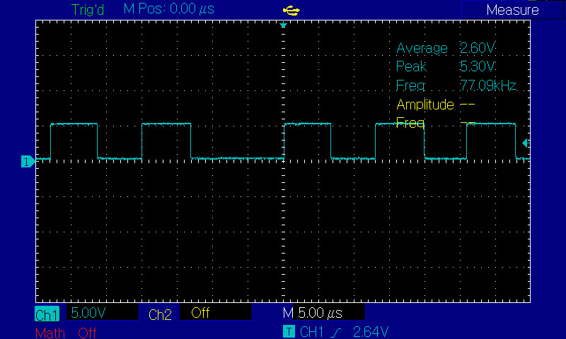
Notice that I connected only one pin. When I do this for other pins at the same time we will get smaller frequency. This indicates that these interfaces based on gpio won’t run at high speed.